This manual was prepared to provide instructions on the operational procedures to be applied on worksites for the prestressing of tie rods.
The execution of the prestressing must follow the instructions of the containment project, contemplating the designer’s guidelines in accordance with NBR 5629/2018.
1 – Prestressing Steels
Steels for prestressed concrete have been manufactured in Brazil since 1952 by Belgo Bekaert Arames within the highest quality standards, meeting the specifications regarding yield and rupture limits, as well as the expected elongations.
The characteristics for relieved (RN) and stabilized (RB) prestressing wires must comply with the ABNT 7482, ASTM A 421 and BS 2691 Standards.
If there is any doubt about the characteristics of the steel, it must be subjected to tests to ensure its mechanical characteristics. The results obtained in the tensile, elongation and ultimate limit test must then be compared with the characteristics provided by the manufacturer.
2 – Regarding the Transport of the Coils
Special care must be taken in transporting the steel between the mill and the distributor, as well as between the distributor and the construction site, and the packaging must be carried out in a way that offers safe conditions, so that the coil is not damaged. Likewise, the steel coil must be covered with canvas during transport, in order to avoid contact with water, so as not to trigger a corrosive process.
3 – Steel Receipt Details
Check if the weight informed on the invoice is the same as indicated on the Arcelor identification plate that comes affixed to the coil, keep this label it contains important information about manufacturing, Steel Type and Diameter, Lot/Manufacturing Order No., Length and Net weight received.
Check that the steel does not show surface damage, oxidation or oiliness, aspects that can impair not only the performance under load but also the adhesion with cement grout.
4 – Coil Storage
Make sure that the coils are stored in a covered place, if it is not possible to cover them with a waterproof canvas. Away from volatile chemicals, which vapors can promote steel oxidation. Keep a minimum distance between the coil and the ground of at least 30 cm.
If the coils can be stored for a longer period, it may be necessary to use a surface protection based on soluble mineral oil, for example Dromus BL – Shell or similar;
5 – Tie Rod Mounting
Prevent dragging the strand over abrasive surfaces after cutting.
Steel can only be cut when cold, using a manual sander/grinder with a cutting disc, or a multi-cutting machine; Using a torch for cutting is prohibited, as it will change the physical properties of the steel due to the heat.
Try to start cutting with the longest cables in order to minimize losses in the coil.
On the bench, observe if the strands have bends or twists (straightening of the steel is prohibited).
If there are any oxidation spots, these must be removed by mechanical sanding with rotating steel brushes or by hand, leaving the surface polished and free from corrosion.
The surface of the cables must be free from oil, grease or any other material that could impair the adhesion of the cables with the grout. For removal, use solvent and tow;
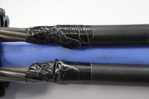
In the case of anchor rods, the free section that is covered by a HDPE tube (spaghetti) must be watertight against the entry of cement grout from the injections. To this end, the end of the tube at the boundary between the free section and the anchored section must be sealed using plastic adhesive tape reinforced with a polyamide weave such as TECTAPE FLEX 48mm or similar.
6 – Use of Collective Sheaths
The collective sheath, according to item C.4.- Anticorrosive Barriers, see NBR 5629/2018, must be defined by the designer based on the information received about the degree of aggressiveness of the rock mass, must be resistant to degradation and watertight to injection, therefore, between the free section and the anchored section, they must be sealed internally to the tube, composed of expandable polyurethane and reinforced, TECTAPE FLEX type, 48mm adhesive tape.
7 – General Guidelines on the Assembly Process for Prestressing
7.1 SAFETY
Demarcate a safety area in order to allow only trained employees involved in the prestressing activity to remain with the equipment during the process.
Never allow the positioning of employees or equipment traffic in the alignment of the hydraulic cylinder (back) during the prestressing operation. There is a risk that the strand under tension may break during the process, which can lead to a serious accident.
7.2 BLOCKS, WEDGES AND PLATES
- The use of anchor blocks with wedges from another manufacturer or vice versa, can generate incompatibility in the prestressing process, as both are part of an ANCHORAGE SYSTEM that, together with the cylinder accessories, were dimensioned to work together;
- Never reuse wedges;
- Never use wedges of different dimensions or manufacturers in the same anchor block;
- Check in advance if the wedges to be used are NEW, if they do not have cracks or defective internal grooves, if they are free of dirt, grease or oil adhered, if not, DO NOT USE this part in the prestressing of the tie rods;
- Check if the support plates are centralized, that is, with the central hole centered on the tie rod, so that the strands, when tensioned, do not touch the internal edges, generating risk of rupture by friction;
- Check if the anchor blocks are free of dirt and without irregularities, especially inside the wedge housing cones;
7.3 – CHECKS OF THE HYDRAULIC PRESTRESSING ASSEMBLY
- Check in advance if the stroke of the piston of the hydraulic cylinder to be used is compatible with the expected deformations of the tie rod during the test;
- Check if the pressure gauge is within the validity period of calibration, through a specific adhesive attached to its body, which must also accompany the measurement certificate issued;
- Check if the hydraulic pump and cylinder are in perfect working order, make sure the pump oil level is at the correct operating level, otherwise, supplement with the hydraulic oil recommended by the pump manufacturer. Never mix oil or use contaminated used oil, under penalty of severe damage to pump components;
- Check if the hydraulic hoses are connected to the correct inlet and return positions of the hydraulic cylinder; Before connection, clean the connections/quick couplers with a clean cloth, to avoid contamination of the system with soil particles;
- Check if the hydraulic cylinder area, normally engraved in low relief on the cylinder body, is compatible with the information provided by the equipment rental company and/or described in the Measurement Certificate, if any;
7.4 – CABLE PREPARATION AND INJECTION CURING VERIFICATION
- Make sure that the last stage of grout injection applied to the tie rod has reached the curing time compatible with the cement used, in order to acquire the minimum compressive strength, as well as the adhesion necessary for the execution of the prestressing test;
- Curing Times: Using CP II cement 32 = 7 days and for CP V-ARI = 4 days;
- The strands at the outer end of the tie rod (pigtail) must be clean, free from cement cream, excessive oxidation, oiliness, in order to guarantee perfect wedge x strand adhesion, especially in the region next to the block. Clean with water or solvent as a guarantee;
- When installing the tie rod, leave the external pigtail with a length L= 1.00 m from the curtain or wall face. For provisional curtains, where metallic stringers will be used, the length of the external section must be L= 1.50 m to allow the installation of the stringer plus the coupling of the cylinder and its accessories;
7.5 – ASSEMBLY OF THE PRESTRESSING SYSTEM, CYLINDER AND ACCESSORIES
- Make sure that the installation of the hydraulic cylinder, wedges and driving foot are perfectly supported on the block, thus avoiding that when starting prestressing some cables are stretched before the others.
- Always leave the cylinder piston open about 15mm before attaching the wedges, as this recoil may be necessary for the complete dislodgement of the wedges after prestressing;
- Install the prestressing block, taking care to insert the cables without intertwining, that is, maintaining the straight alignment of the cables coming out of the curtain;
- Install the wedges, fixing them to the block with the aid of the driving “hammer”;
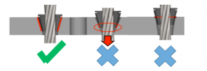
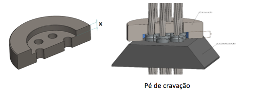
- Install the driving foot with the recess face facing the wedges. In the same way as before, do not twist the strands keeping the same block output alignment. For wedges and Incotep block for 12.7mm strands, the height of the recess of the driving foot is 8.5mm, this recess is essential and was dimensioned so that the driving of the wedges occurs correctly. See figure below.
- Use paraffin on the external side of the WEDGES, that is, tension wedges of the cylinder head, to facilitate their removal after the test;
7.6 – CORRECT WAY TO ASSEMBLY THE CYLINDER AND ACCESSORIES ON THE TIE ROD
- IT IS WRONG to assemble the cylinder by lifting it with the help of some tension wedges, to align it with the angle of the tie rod.
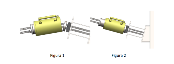
THE CORRECT PROCEDURE IS:
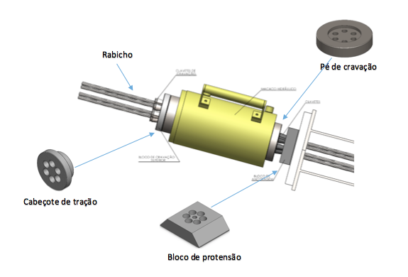
- Install the block, wedges, driving foot, cylinder, traction head and the tension wedges, positioning the set in the same alignment as the tie rod and supporting the whole with a wooden prop;
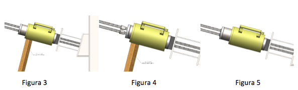
- Activate the pump by positioning the cylinder (figure 3);
- Keeping the cylinder supported, withdraw the cylinder piston in order to relieve the tension wedges, repositioning them correctly in the housings (figures 4 and 5);
- Activate the cylinder, bring it to the Initial Fo load, remove the support and start the prestressing and/or test;
- Thus, when prestressing begins, all strands will be at the same tension level.
NOTA: To carry out the RECEIPT TESTS, use the U-type device between the block and the driving foot.
7.7 – Cutting the external section, pigtail after prestressing
- For Definitive Tie rods, after the completion of the reception tests and prestressing for load incorporation, the respective prestressing reports must be prepared and presented to the customer/designer for approval and release for tail cutting.
- Once the tie is released, cut the tail, leaving approximately 4 cm of tip after the face of the wedge. The cut must be done cold, using a cutting disc and sander.
- For Provisional Tie Rods, after incorporation of the load, the remaining external pigtails must be gathered in a single bundle, secured with annealed wire and even better, if wrapped in empty cement bags. This measure aims to preserve the cables against collisions with equipment during excavations, preventing the strands of wires from unraveling as well as from entering a process of severe corrosion, preventing any REPRESTRESSING if necessary;
- Impacts on the strands caused by excavator buckets, for example, can cause the wedges to loosen in their housing, resulting in partial or even total loss of prestressing load.
7.8 – About Reusing the Anchoring Blocks
It is possible to reuse the anchor blocks more than once. However, some assumptions must be observed, namely:
It is essential to clean the blocks with a high pressure washer using hot water. If the blocks are very oxidized, especially inside the conical housings of the wedges, the ideal would be to submit them to a pickling process, which aims to remove oxidation and encrustations;
After cleaning, perform individual inspection of the blocks for deformations or warping, with emphasis on checking the interior of the wedge housings. This check must look for anomalies, deformations, dimensional irregularities or excessive roughness, which may compromise or prevent the performance of the wedges;
If the aforementioned anomalies are checked, the blocks must be condemned and discarded.
Approved blocks must receive a protective layer against corrosion and stored in a covered place.
We emphasize that the reuse of wedges is unacceptable and can lead to losses of all kinds.