Hollow
Produced from seamless tubes, they also undergo a cold rolling process to form the continuous thread with an exclusive profile.
Incotep Hollow have as their main characteristic their high mechanical strength, which, combined with their hollow section, allows the rod to act simultaneously as a drilling and injection rod.
For drilling, a special tricone drill is coupled, which will be incorporated into the rod, equipped with directional holes that inject the cement grout under pressure, allowing the formation of the anchoring bulb with a variable diameter between 200 and 300mm, depending on the rock mass profile where the tie will be anchored.
The installation of the Hollow is also possible in mixed soil/rock or rock mass only, simply by attaching a drill bit with carbide buttons, also supplied by Incotep.
In this way, at the end of the drilling process, the bolt will be automatically installed and injected, a methodology that gives the Hollow System a substantial gain in time in relation to the conventional anchoring process.

Description
Technical Characteristics – Tubular System
| Hollow | Diameter | Thickness [mm] | Area [mm²] | Linear Mass [Kg/m] | Minimum Mechanical Properties [Kgf/mm²] | Loads [Tf] | |||||||
|---|---|---|---|---|---|---|---|---|---|---|---|---|---|
| Limit Loads | Work according to ABNT NBR 5629:2018 | ||||||||||||
| Nominal [mm] | Effective [mm] | Flow Limit | Burst Limit | Yield Load | Ultimate Load | Assay | Permanent | Provisional | Prova de Carga | ||||
| INCO 15TD | 40 | 38,1 | 7,0 | 684,0 | 5,37 | 44,0 | 58,0 | 30,0 | 40,0 | 27,0 | 15,0 | 17,0 | 22,6 |
| INCO 20TD | 40 | 38,1 | 9,0 | 822,0 | 6,45 | 47,0 | 60,0 | 38,6 | 49,0 | 34,7 | 20,0 | 23,0 | 28,9 |
| INCO 27TD | 40 | 38,1 | 9,0 | 822,0 | 6,45 | 63,0 | 74,0 | 51,8 | 60,0 | 46,6 | 27,0 | 31,0 | 38,8 |
| INCO 34TD | 40 | 38,1 | 11,0 | 936,0 | 7,35 | 70,0 | 83,0 | 65,5 | 77,0 | 59,0 | 34,0 | 40,0 | 49,2 |
| INCO 43TD | 50 | 48,3 | 11,5 | 1330,0 | 10,44 | 63,0 | 74,0 | 83,8 | 98,0 | 75,4 | 43,0 | 50,0 | 62,8 |
| INCO 51TD | 50 | 48,3 | 15,0 | 1569,0 | 12,32 | 63,0 | 74,0 | 98,8 | 116,0 | 88,9 | 51,0 | 59,0 | 74,1 |
| INCO 70TD | 62 | 60,3 | 15,0 | 2134,0 | 16,76 | 63,0 | 74,0 | 134,4 | 158,0 | 121,0 | 70,0 | 80,0 | 100,8 |
Remark: Elasticity Module 21,000 Kgf/mm².
| According to ABNT NBR 5629:2018 | |||||||||||||
|---|---|---|---|---|---|---|---|---|---|---|---|---|---|
| Maximum test load | = 0.90 x yield load | ||||||||||||
| Permanent workload | = test load / 1.75 | ||||||||||||
| Provisional workload | = test load / 1.50 | ||||||||||||
| Load test or short duration loads | = test load / 1.20 | ||||||||||||
Splice Sleeve
| System | Diameter D [mm] | Length L [mm] |
|---|---|---|
| INCO 15TD | 60,3 | 160,0 |
| INCO 20TD | 60,3 | 160,0 |
| INCO 27TD | 60,3 | 160,0 |
| INCO 34TD | 60,3 | 160,0 |
| INCO 43TD | 73,0 | 180,0 |
| INCO 51TD | 73,0 | 180,0 |
| INCO 70TD | 88,9 | 210,0 |

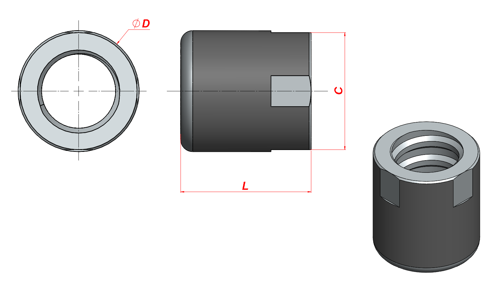
Anchor Nut

| System | Diameter D [mm] | Length L [mm] | Key dimension C [mm] |
|---|---|---|---|
| INCO 15TD | 60,3 | 65,0 | 58,0 |
| INCO 20TD | 60,3 | 65,0 | 58,0 |
| INCO 27TD | 60,3 | 65,0 | 58,0 |
| INCO 34TD | 60,3 | 65,0 | 58,0 |
| INCO 43TD | 73,0 | 80,0 | 69,0 |
| INCO 51TD | 73,0 | 80,0 | 69,0 |
| INCO 70TD | 88,9 | 100,0 | 85,0 |
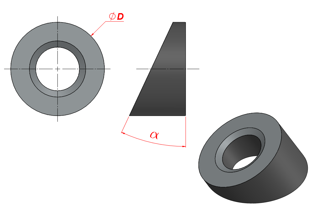
Degree Ring
| System | Diameter D [mm] | Angle α [Degree] |
|---|---|---|
| INCO 15TD | 96,5 | 5°| 10°| 15°| 20°| 25°| 30°| 35°| 40°| 45° |
| INCO 20TD | 96,5 | |
| INCO 27TD | 96,5 | |
| INCO 34TD | 96,5 | |
| INCO 43TD | 96,5 | |
| INCO 51TD | 96,5 | |
| INCO 70TD | 121,0 |

It is recommended to use a lock nut when the tie rod is permanent.
Anchoring Plate

| System | Dimensions L [mm] x L [mm] | Thickness and [mm] |
|---|---|---|
| INCO 15TD | 200 x 200 | 15,9 |
| INCO 20TD | 200 x 200 | 15,9 |
| INCO 27 TD | 200 x 200 | 19,0 |
| INCO 34TD | 200 x 200 | 19,0 |
| INCO 43TD | 200 x 200 | 22,2 |
| INCO 51TD | 225 x 225 | 25,4 |
| INCO 70TD | 250 x 250 | 38,1 |
Lock Nut
| System | Diameter D [mm] | Length L [mm] | Key dimension C [mm] |
|---|---|---|---|
| INCO 15TD | 60,3 | 30,0 | 58,0 |
| INCO 20TD | 60,3 | 30,0 | 58,0 |
| INCO 27TD | 60,3 | 30,0 | 58,0 |
| INCO 34TD | 60,3 | 30,0 | 58,0 |
| INCO 43TD | 73,0 | 40,0 | 69,0 |
| INCO 51TD | 73,0 | 50,0 | 69,0 |
| INCO 70TD | 88,9 | 50,0 | 85,0 |

Button Drill

| Soil / Gravel Type | Drill Diameter [mm] |
|---|---|
| INCO 15TD | 87 |
| INCO 20TD | 87 |
| INCO 27TD | 87 |
| INCO 34TD | 87 |
Tricone
| Soil Type | Ø Tricone [mm] | Ø Holes [mm] | Angle β |
|---|---|---|---|
| Clay | 110 a 130 | 4 – 5 | 90° |
| Silt | 130 a 150 | 5 – 6 | 90° |
| Sand | 130 a 180 | 6 – 8 | 45° |
![]()
Calculation of Load Capacity of Hollow
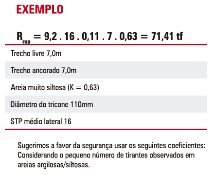
The load capacity of the anchorage of Self-Injection Rods can be calculated by the formula developed by engineers Ivan Joppert Jr., William Mallmann, and Walter Iório, presented in SEFE V, assuming the ultimate load, being:


We suggest in favor of safety to use the following coefficients: Considering the small number of tie rods observed in clayey/silty sands.
| Soil | K [t/m²] |
|---|---|
| Little clayey sand | 0,42 |
| Little silty sand | 0,50 |
| Very clayey sand | 0,68 |
| Very silty sand | 0,63 |
| Sand | 0,30 |
| Soil | K [t/m²] |
|---|---|
| Clay | 1,00 |
| Silty clay | 1,00 |
| Little sandy clay | 1,00 |
| Sandy silt | 1,00 |
| Soil | K [t/m²] |
|---|---|
| Very clayey / silty sands | 0,60 |
| Very clayey / silty sands | 0,40 |
Executive Methodology
Incotep Hollow are performed through the following steps:
1st Step – Assembly
The assembly of the Incotep Self-Injection Rods is very simple and fast, as the bars, sleeves, drills and other accessories are supplied by the factory, simply assembling the rod at the work site;
It is recommended to leave an easel with the drill rig with the mounted rod segments necessary for the rod to be executed, especially the segments of the free section that must receive a layer of grease and be coated with the sheath, HDPE tube, connected to the splicing sleeve;
Assembly starts by connecting the tricone bit or drill bit to the end of the first bar to be introduced into the ground. The other bars are connected in sequence, as the drilling progresses, interconnecting the bar segments through the splicing sleeves.
In the anchored section (bare bars), loose spacers are used in order to avoid breaking them.

Figure 1 – Start bar coupled with drill bit

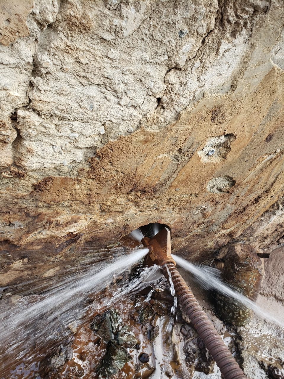
Figure 2 – Start of drilling, water flowing at the tip of the drill bit

Figure 3 – It can be seen in the photo, the hole already started, and in the detail, the grout injection head, coupled below the rotopercussive drill (surface hammer). The testine, or water head, will insert the cement grout on the rods of the tie rod for simultaneous drilling and injection.

Figure 4 – Drilling in progress, with water circulation and after, injection of cement grout for anchor injection.
2nd stage – Drilling with Simultaneous Injection
The tie rod is introduced into the ground with the aid of a rotary or rotopercussive drill, with a minimum torque of 500 kgf.m. It is recommended that the rotation to implant the rod in the ground is between 50 and 90rpm and that the drilling advance is between 0.50 and 1.50m/min or. In cases where a rotopercussive drill is used, a compressor of 750pcm and 10bar pressure is recommended
Simultaneously with the drilling of the tie rod, the cement grout is injected (f a/c between 0.75 and 0.50) under pressure, through a device of the water head type, coupled to the rods just below the rotator of the drill, making it flow to the tricone drill where it will exit through the directional holes forming the anchor bulb.
In the section corresponding to the free section, the fluid is composed of a “thin” grout of water and cement with a water-cement factor f a/c = 0.75 for cleaning and stabilizing the hole. In the anchored section, the cement grout must have f a/c =0.50, injected with a minimum pressure of 30 kgf/cm².
The cement grout injection pressure is a very important item in the formation of the anchor bulb. In sandy rock masses, mixing the grout with sand is essential for anchoring, as well as, in cohesive materials such as clay, cleaning the hole is essential in the anchored section so as not to contaminate the cement grout. The drilling parameters and viscosity of the cement grout must therefore be suitable for the rock mass to be drilled.
3rd Stage – Prestressing
After the installation and simultaneous injection of the tie rod, it is only necessary to wait for the curing time of the cement grout according to the type used, being 4 days for the CPV ARI cement or 7 days, if you have used the CP II 32 Portland cement, for then perform the pretension.
The prestressing of the Self-Injection Rod is carried out with the aid of the hydraulic cylinder/pump set as in the other tie rods, observing the test loads and displacements in accordance with NBR 5629-18.
The complementary accessories that make up the tie rod anchoring head are the support plate, degree ring, and the mounting nut.
Incotep has developed a PRESTRESSING KIT, to be used in prestressing, composed of a splicing sleeve, a 1000mm splice bar and a treated flange nut, which allows the prestressing of up to 40 rods without the need to leave an extension of external bars on each rod, reflecting up to 40m of savings in the bars.
Consult our team and find out about this innovation
Figure 5 – Schematic of the Self-Injection Rod tether and its components


